Niges MK2 Golf Track car build in 5 weeks.. MASSIVE Thread !

Show us yours....
Nige
Posts: 122
Joined: Fri Sep 01, 2006 6:55 pm
Location: Mirfield, West Yorkshire

Post by Nige »

When I`d swapped one of the brake disks, the Bolt holding the carrier to the hub was stuck and rounded the head off. I ended up having to hammer a 16mm socket onto the head to get it off.
Image

New bolt had to be ordered, not in stock ! Picked it up from the main dealer. Next to the old one, you can see how mangled the head is.
Image

Changed the timing belt and tensioner today as a precautionary measure. For

Nige
Posts: 122
Joined: Fri Sep 01, 2006 6:55 pm
Location: Mirfield, West Yorkshire

Post by Nige »

Long overdue update. One of a few as I`m doing a fair bit at the moment.

This update is about the gearbox mount I made. I`ve read many posts on them and Steve_R kindly sent me a spare mount he had aquired.
Image

Cut away the old bracket and was left with the bush and rubber mount
Image

Camera battery died, so by the time it had recharged, I`d almost finished. I cut the clutch cable bracket, kept the part I needed to secure the Clutch cable, then welded that to my new bracket.

As I only have a Vice, Hammer, Angle Grinder and Welder, my fabricating skills may not be quite as good as they could be, however, after bending the plate 90 degrees, I realised I couldnt bend the next part, so I left it as a letter `L`, then welded on a flat piece to complete the `U` shape I was after.
Image

As the rubber was in the sleeve, when welding the support arms to the sleeve, I welded a few seconds then dunked it all in a bucket to cool it and protect the rubber.
Image

Welded some plate to the chassis leg
Image

Then mounted the bracket on the gearbox to enable correct placing of the 2 plates to support the mount.
Image

I then welded the 2 plates to the chassis leg
Image

I was concerned the plates would flex side to side, so I cut some more plate and bent it.
Image

This was then welded into plate to significantly strengthen the whole bracket
Image
Image

A few coats of matt black for the bracket
Image

Here you can see the captive nut I welded on the back.
Image

Paint the chassis leg mount
Image

Then attach the whole thing together.
Image

Hopefully this will help keep the engine from moving so much. [:y:]

Nige
Posts: 122
Joined: Fri Sep 01, 2006 6:55 pm
Location: Mirfield, West Yorkshire

Post by Nige »

After my`moment` at Oulton and a general dissatisfaction with the vague cable change, I took a mate`s advice and went down the MK4 shifter route. I sourced a MK4 shifter tower and cables from the classifieds on ClubGTi. When I`d bought my low ratio gearbox, SAMBO had very kindly given me a MK4 tower he had no use for [:y:]

MK3 Shifter and cables and MK4 shifter and cables with `ball` ends.
Image

First job fit MK4 tower. AH a problem already (but not unexpected, I`d already heard of this). The MK4 Shofter reversing switch fouls the cable clutch bracket.
Image

Easy to fix, gring off the bracket.
Image

That leaves a hole for debris to enter and drop into the gearbox. Deciding this was not a good thing, I screwed in a bolt a few threads (with Locktite applied). Be careful not to screw it in too far or it will foul the internal shifter and stop you engaging 5th gear. Not that I did that of course [;)]
Image

Grind off the bolt head
Image

Fit the tower into the gearbox [:y:]
Image

The MK4 gear lever is not threaded, my gearknob is, so I needed to run a Die down the shaft. No problem you may think? hmmm, the shaft had a `kink` in it and believe me, that makes starting a die and absolute PAIN [:x]
Image

I needed to apply ALL my body weight to keep the die horizontal and force it to start a thread.
Image

Once done, a nicely threaded gearshaft
Image

I ran a tap down the gearknob to clean out the threads as my die is M12 x 1.75 and I think the VW spec is M12 x 1.5.
Image

The MK4 shifter is secured differently at the front, so I started to make a bracket out of 2mm plate, then decided that was OTT so used some banding I have in my toolbox, much easier, lighter and ready painted. [:D]
Image

After wrapping a length around the shifter and frame, I secured the ends with a 6mm nut and bolt
Image

One fixed MK4 Shifter with gearknob secured [:)]
Image

Cables attached on the gearbox.
Image

I can report that the shifter IS much better that the MK3 setup. Still not as precise and the rod change in an 020 box, but definately an improvement over the MK3 setup. The shift is precise and weighty, nowhere near as vague as the other was.

Chris Slator gave me some studs for a conversion, threadlocked the studs and double-nutted them into the hubs/disks.
Image

Once done, I applied a spot of tippex and then a tap with a chisel at the nearest point of the stud to the hub. Hopefully a quick glance when checking round will let me know if they are coming loose.
Image

Nige
Posts: 122
Joined: Fri Sep 01, 2006 6:55 pm
Location: Mirfield, West Yorkshire

Post by Nige »

For those that have followed this thread, I`m afraid I`m going to be mentioning the one topic that keeps cropping up. My Exhaust [:x]

After securing the system, I`d drive locally or on UK trackdays and it would be fine, but once on the ring, the Karussel would destroy the exhaust rubbers in a few laps. I tried the rubbers with chains inside them, which helped, but that exhaust would still bang about on the underside of the car which simply wasn`t good enough. It caused me cracked downpipes, split exhaust welds and generally peed me off.

Found a bargain Magnex system on Ebay, like new and for a great price. The seller wouldn`t post, so I think that kept the number of bidders down. Fortunately for me, GVK lived about 6 minutes away and a plan was hatched for him to collect it and then courier it to me [:D]

System arrived and I decided that THIS TIME the damn thing would be right.

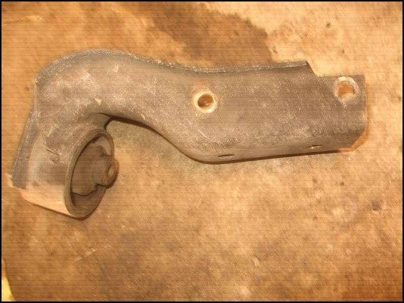
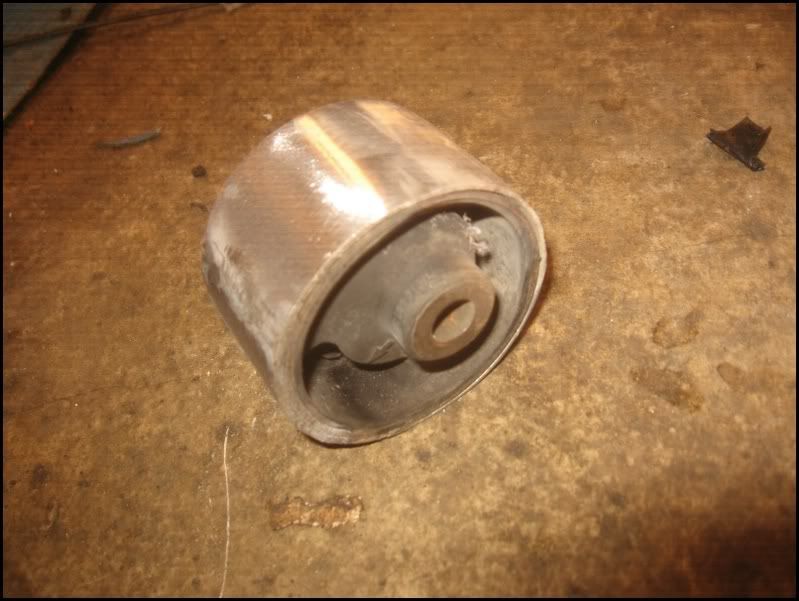
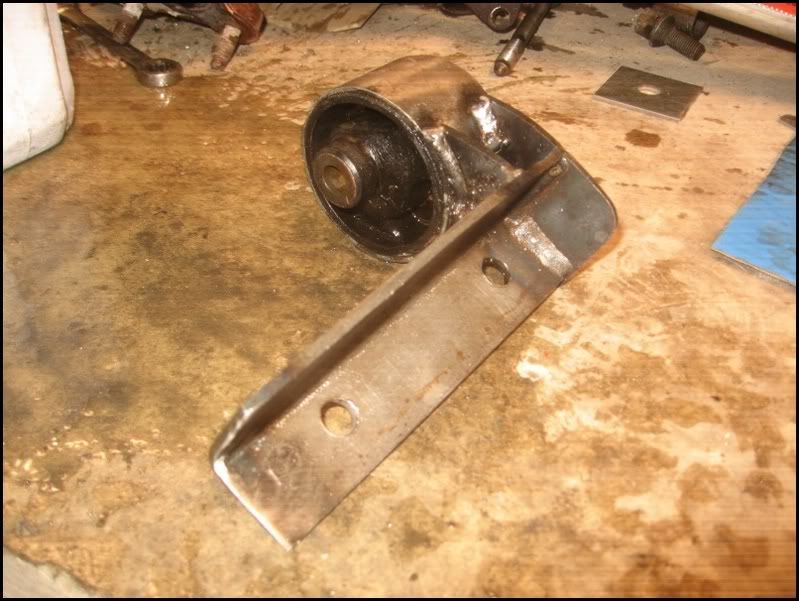
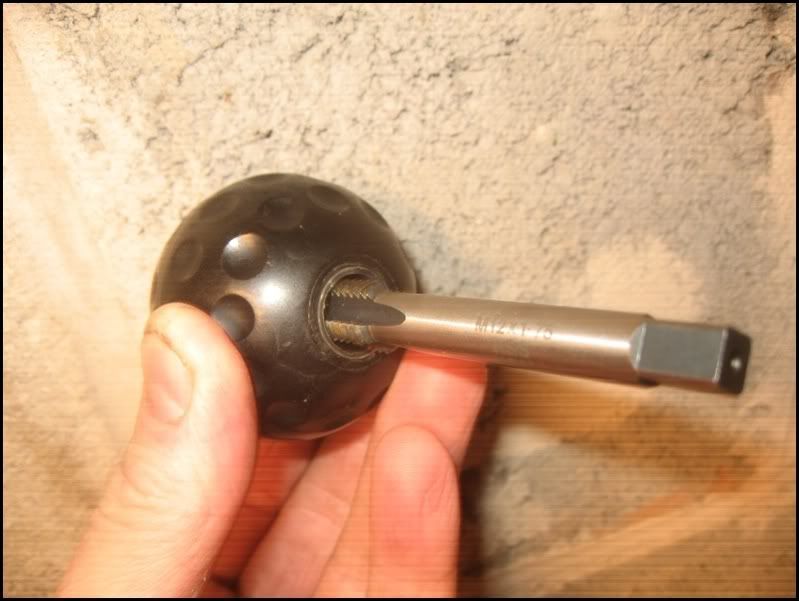
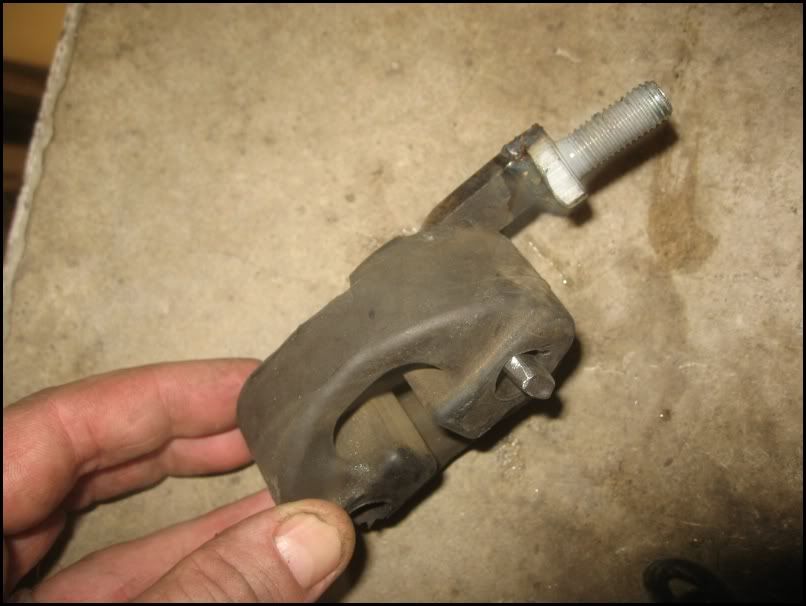
Job one was to aquire some heavy duty rubbers and after talking nicely to my local garage, I went to the exhaust trade only depot nearby and had a look on their shelves. Found this which looked perfect for me. A heavy rubber with built in bracket.
Image

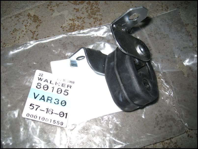
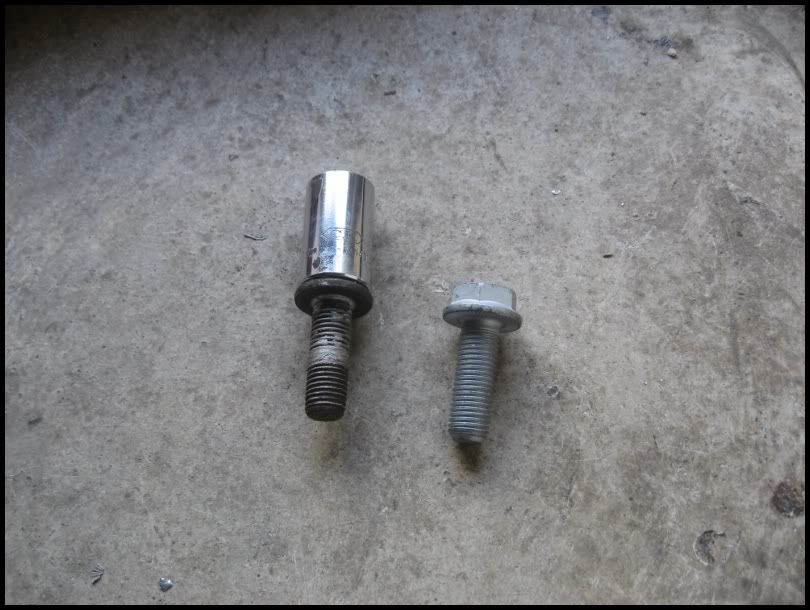
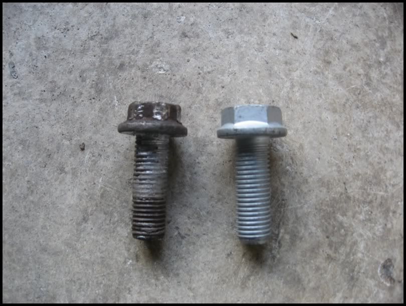
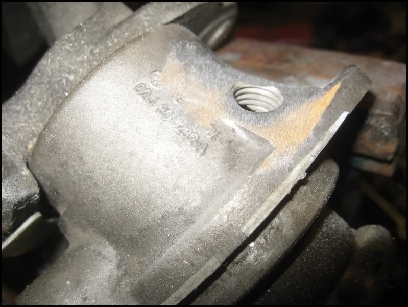
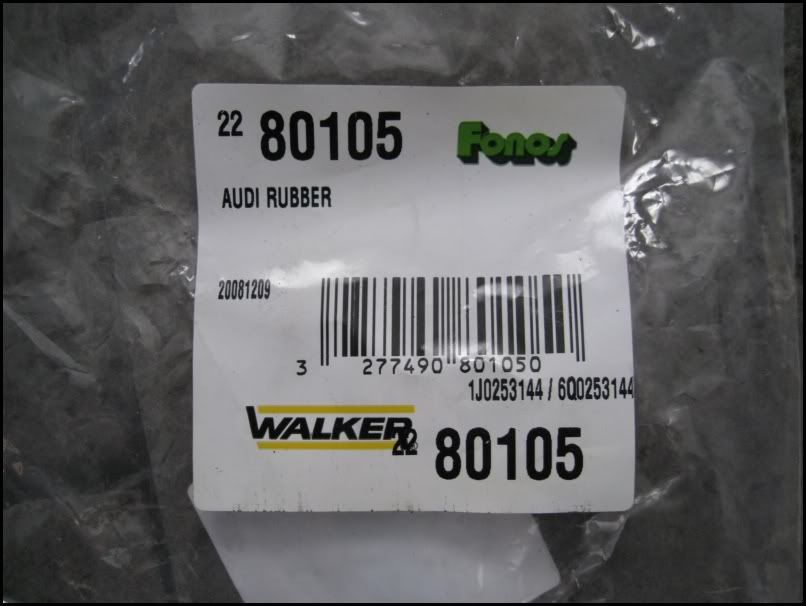
Here are the part numbers if anyone in interested.
Image

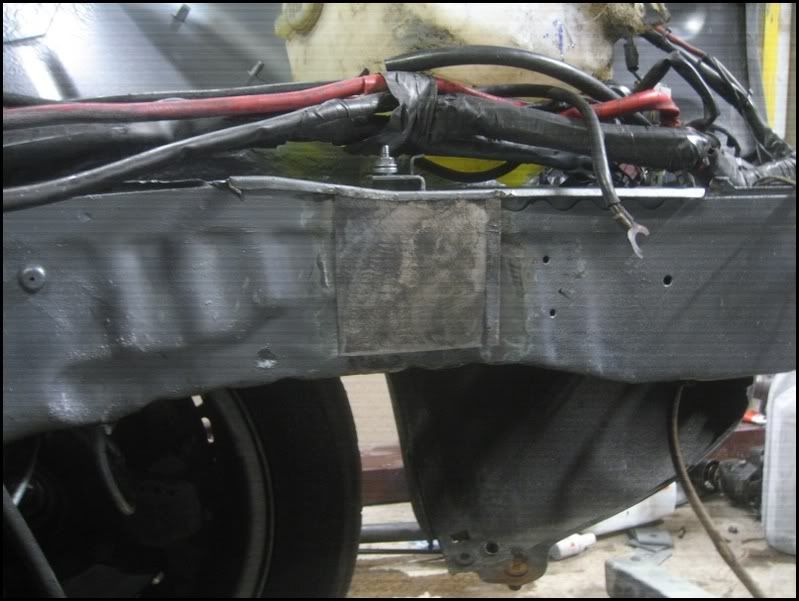
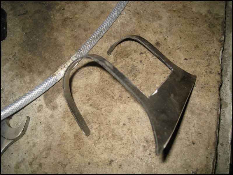
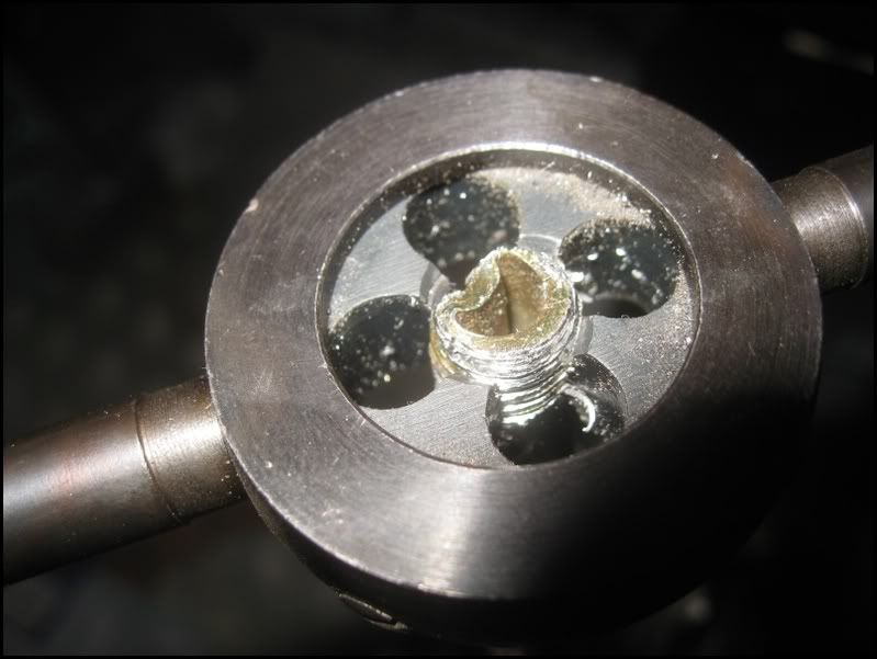
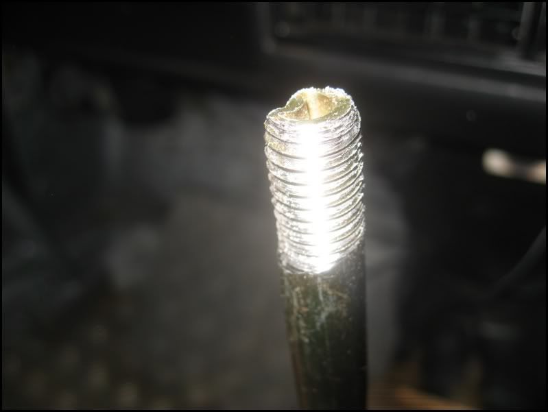
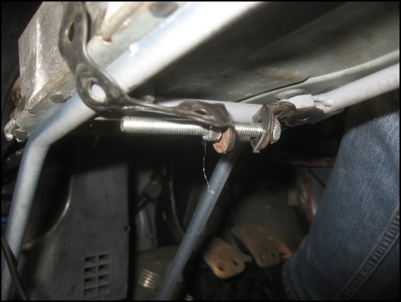
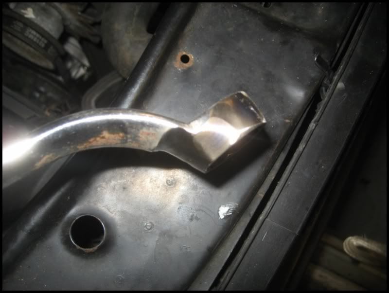
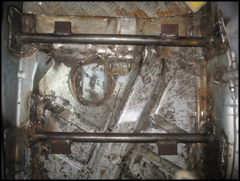
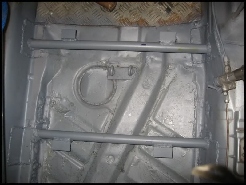
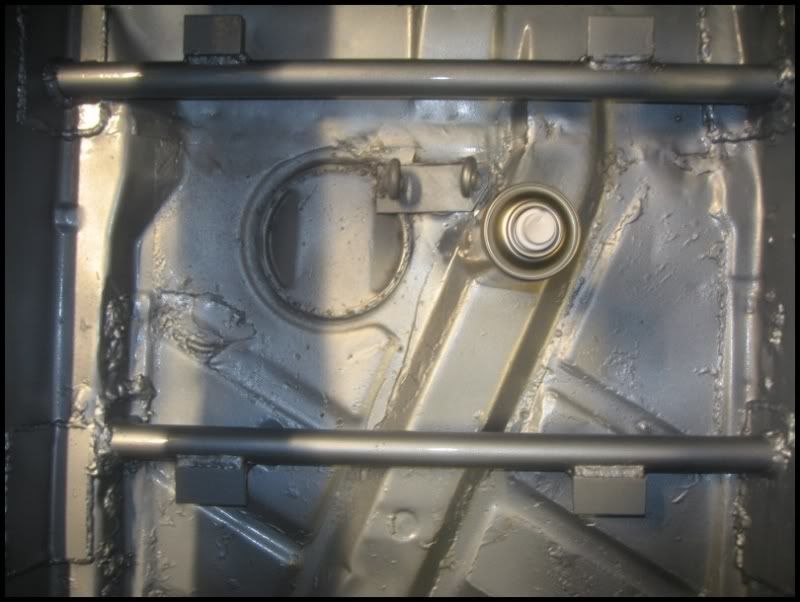
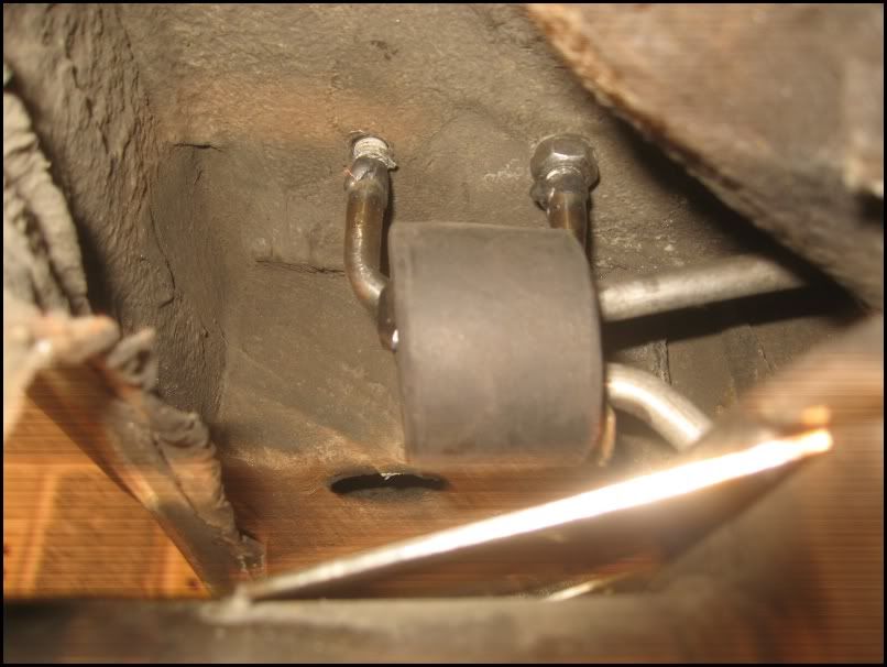
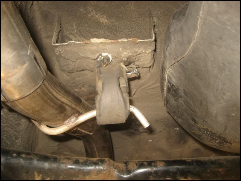
The system came with a large rear mount and bracket. I secured this to the side of the spare wheel well,but it still allowed movement. I welded some 10mm threaded bar to a length of bent 10mm stainless.
Image

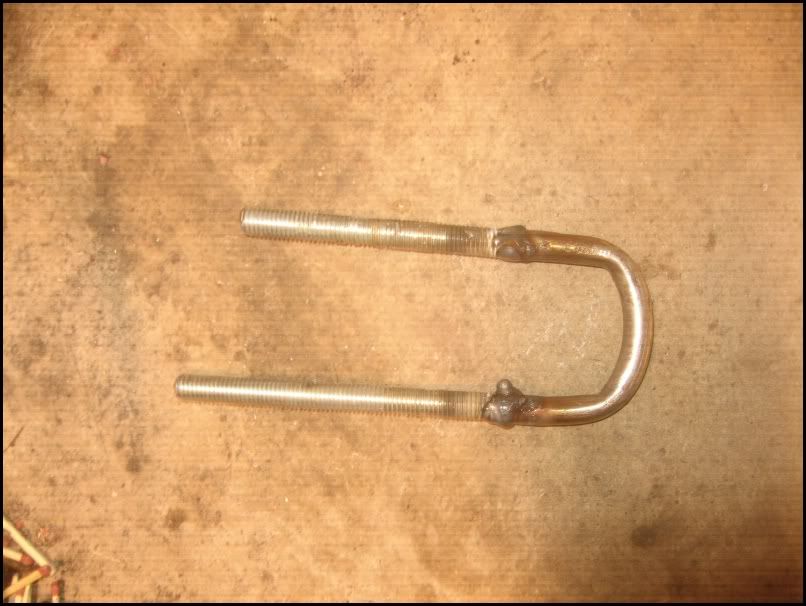
This `U` was threaded through the rubber, then through 2 holes I drilled in the floor of the boot. These were secured with locknuts (I had one on the UNDERSIDE so I could position it vertically). Obviously, all newly drilled holes were painted.
Image
Image

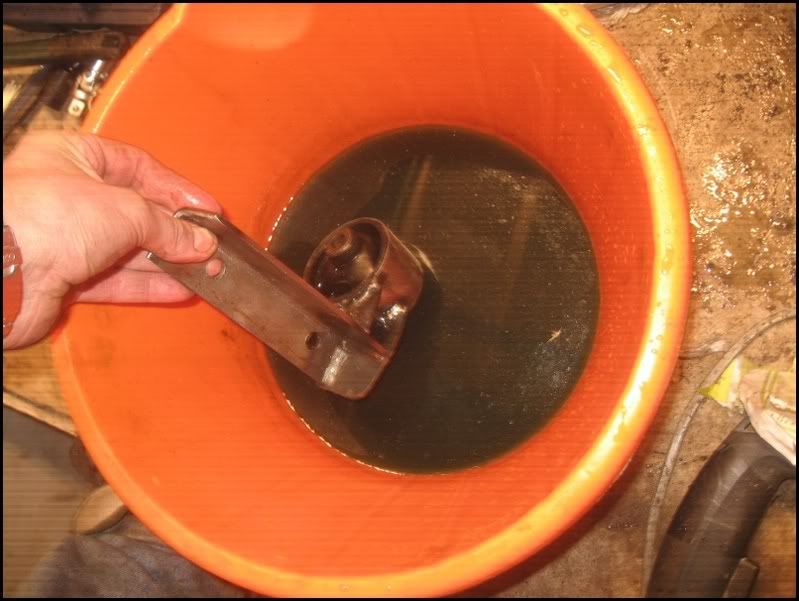
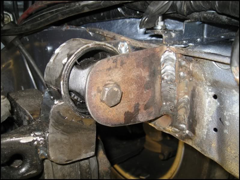
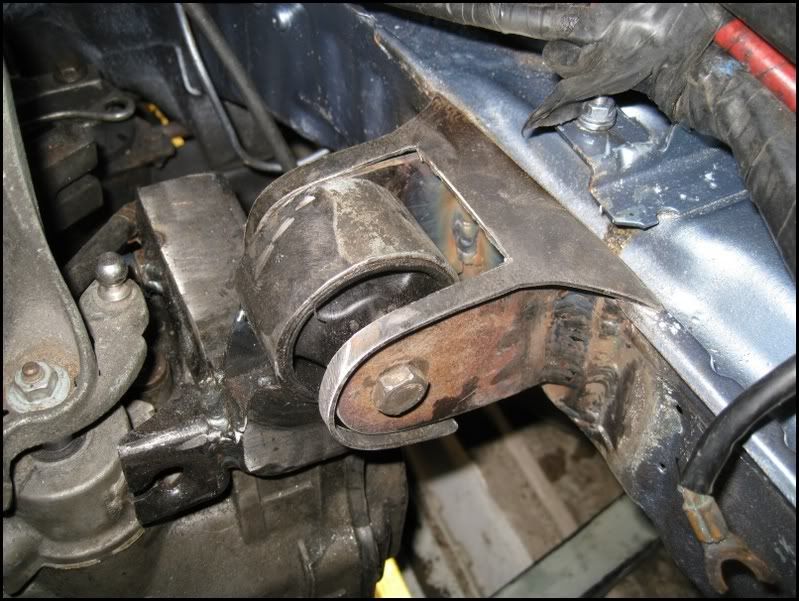
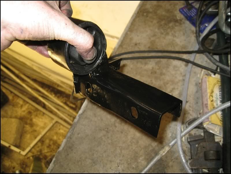
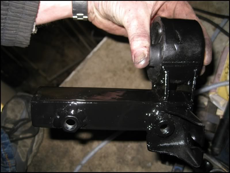
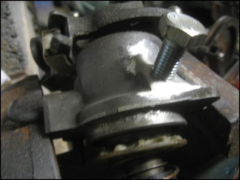
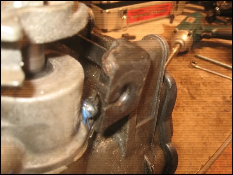
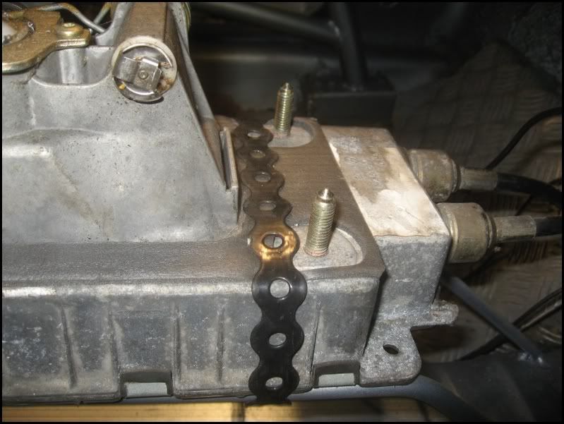
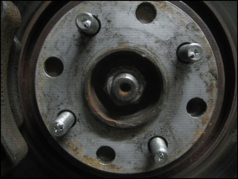
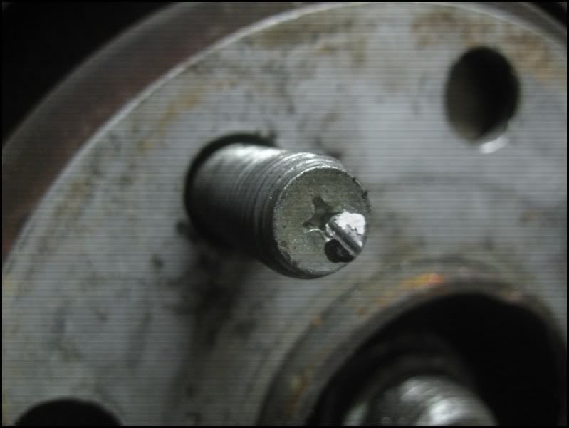
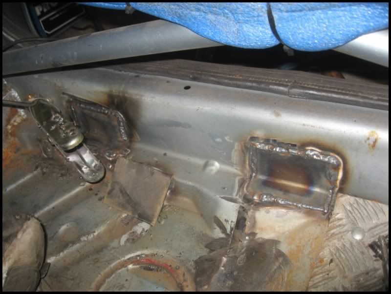
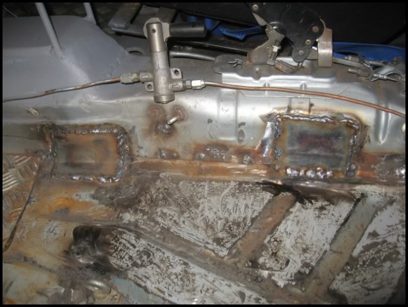
That should be the backbox secured, lets move forward. Using another heavy duty rubber, I decided to make this letter `L` from some plate and weld on a bolt
Image

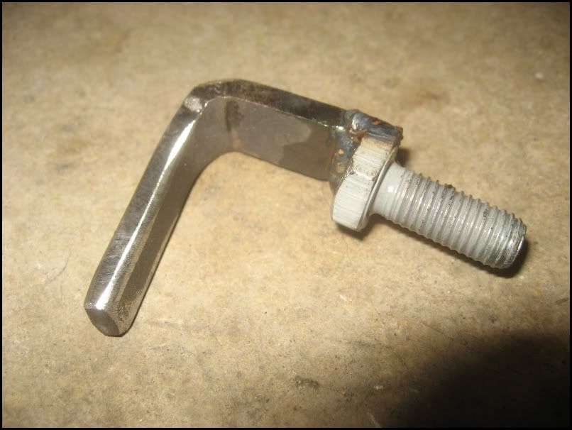
This was then fed through the rubber and afterwards a small locking `leg` welded on to stop it dropping off.
Image

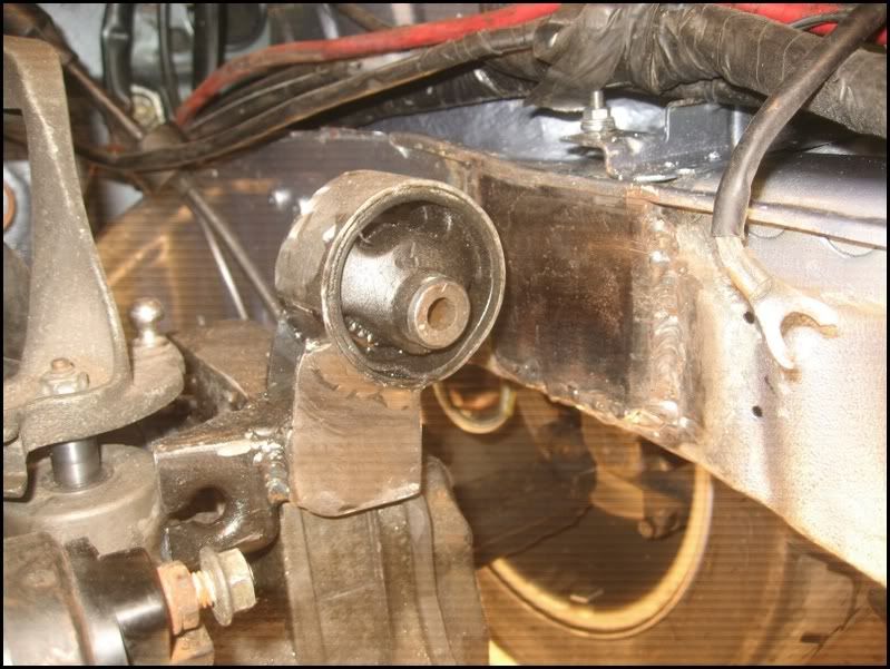
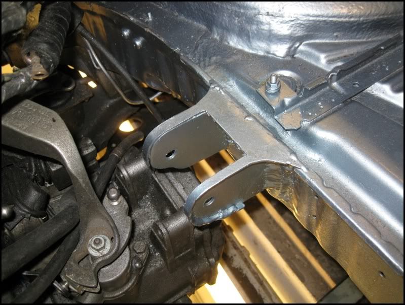
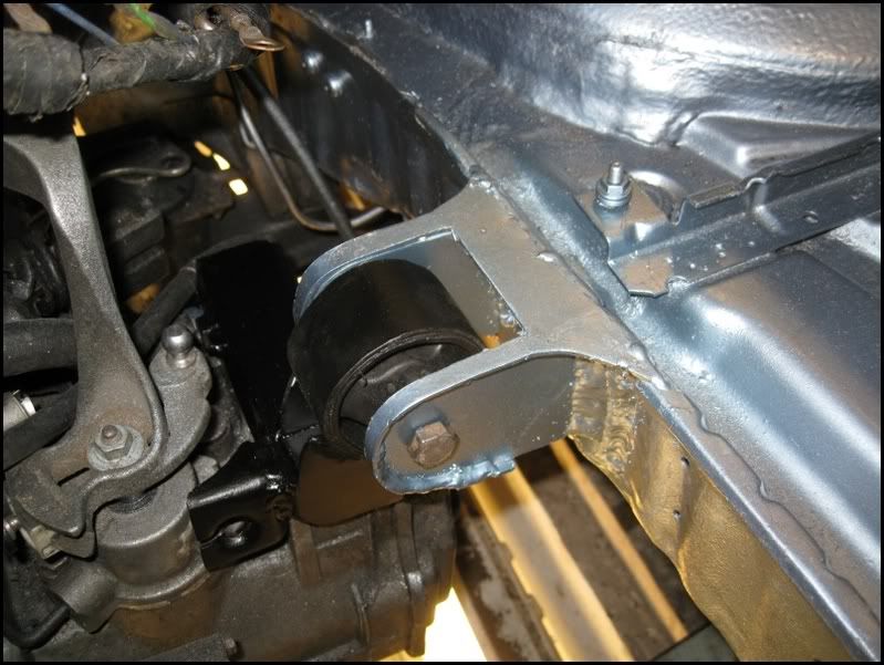
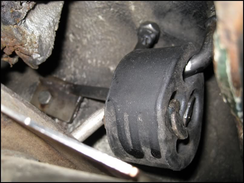
Fortunately, there was already a hole in the chassis, next to the original mount which I could bolt this though using a nyloc nut.
Image
Image

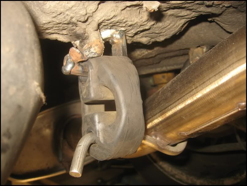
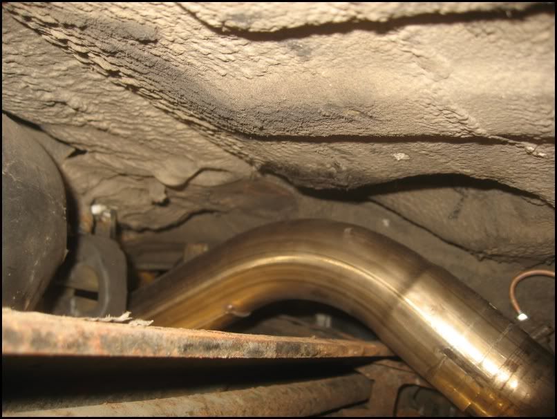
This positioned the bend over the rear beam perfectly.
Image

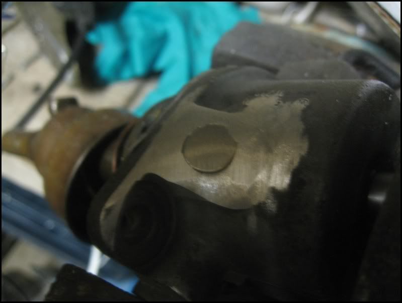
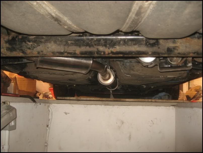
Using my new bracket/rubber, I removed the standard `hook` mounting point and drilled a couple of holes and secured the new mount. Secured the Rubber to the exhaust using a jubilee clip. I didn`t want to start chopping / rewelding the new exhaust and this is very secure.
Image

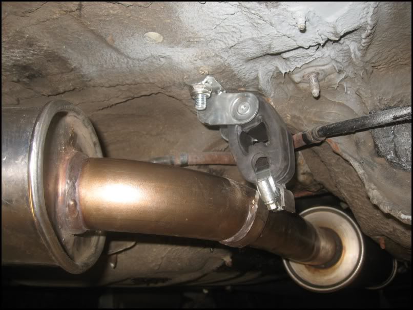
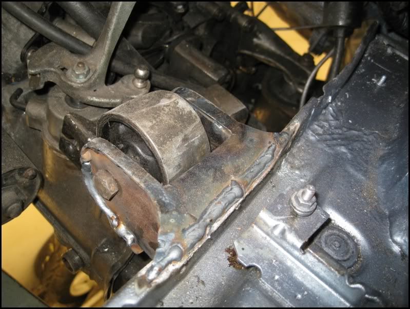
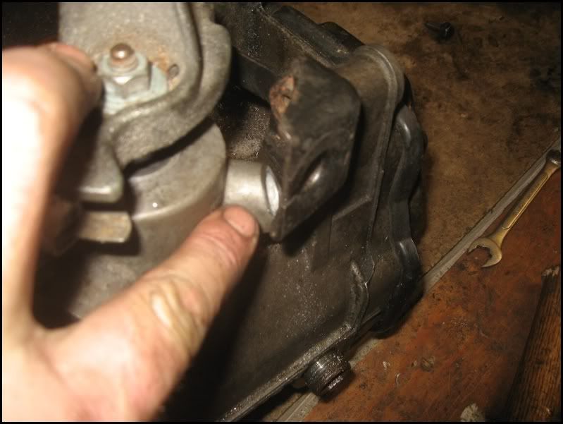
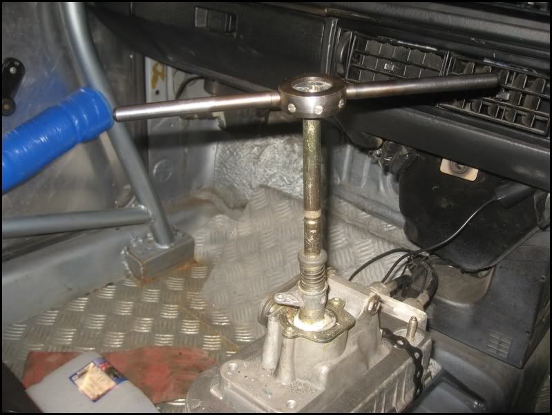
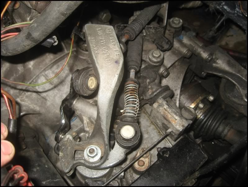
The system sits nicely in the centre of the tunnel, it IS able to move freely on the rubbers, but I hope, it is held in place securely enough to stay in place. The extra mount I added to the gearbox will hopefully limit the engine movement a little too.
Image

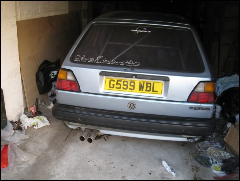
New backbox with smaller twin tailpipes
Image

Will this be good enough? well, I`ll find out at the ring over Easter [LOL]

Tommy
Posts: 633
Joined: Tue Apr 24, 2007 8:09 pm

Post by Tommy »

Nice work Nige. Wish I could fabricate. Well I wish I had a garage too for that matter!

User avatar
RX7
Posts: 5727
Joined: Fri Jul 28, 2006 11:16 am
Location: Norwich

Post by RX7 »

Great update Nige !!!
Good work on all the fabrication.

Look at that list of tracks mate !! That Golf is certainly well travelled from a track point of view !!!!!!!!
--------------------------------------------------------------------------------
Gareth

User avatar
Nik
Posts: 2265
Joined: Sat Oct 07, 2006 1:29 am
Location: March

Post by Nik »

Excellent write up Nige. You certainly know your way round the golf now don't you :)
I may be getting older but I REFUSE to grow up :D
Image

Nige
Posts: 122
Joined: Fri Sep 01, 2006 6:55 pm
Location: Mirfield, West Yorkshire

Post by Nige »

R32 Nik wrote:Excellent write up Nige. You certainly know your way round the golf now don't you :)
I`m getting there :lol:

Changed the Heater Matrix today, no photos, it was a fiddly job, but actually went really well, I now have warm air in the car :). I had bypassed the matrix when it started leaking with a piece of copper pipe, so it was a simple job to reconnect the matrix to the heating system. No photos, sorry.

Wanted to remove the front suspension to change the O/S wheel Bearing today. The top nut was an absolute PAIN to remove... I`m sure with an impact driver, it would come straight off, but I don`t have one (yet...)

Modified offset 22mm spanner with grinder to allow it to fit easier
Image
Image

The 9mm spanner that goes on to the top nut to stop the centre spinning kept slipping off and the jaws were opening slightly !. Welded a half nut at the other end to stop the jaws moving
Image
Image

I could then put the 22mm spanner on the nut, the 9mm on on the centre
Image

I couldn`t hold them both tight enough, so put a bit of wood near the wing, then the centre spanner braced against that and I could REALLY get some weight on the 22mm spanner.
Image

This Worked and I was able to remove the 22mm nut Image

With the front strut / Hub removed, I could theninspect the top mount. I had heard a grinding noise at Elvington and sure enough, the bearing in the top mount had failed
Image

This had allowed the strut top to move, damaging the castellated nut slightly and wearing a groove in it. (New on right)
Image

Decided it was sensible to change the CV joint, seeing as the Hub was removed. Small tip, when filling the CV joint with grease, force the sachet of grease in the CENTRE Hole, once all the grease is in the joint, you`ll see it start to come down the outside, past the balls, highlighted by the screwdriver. This means the grease is where it should be, ie in the Joint, not in the rubber.
Image

Refitted new CV and am pressing in new Bearing tonight. i`ll then change both top mounts for uprated G60 ones.

I`m currently in the process of fitting welded seat rails to lower the seat a few inches, but I`ll post all the photos at once.

Oh, I didn`t cut my head this time [:^:]

I just slipped and cut my finger, on the joint, deeply... very deeply actually [XXX]
Image

Nige
Posts: 122
Joined: Fri Sep 01, 2006 6:55 pm
Location: Mirfield, West Yorkshire

Post by Nige »

Decided I really should get my Compomotives refurbed. Stan had the tyres removed for me (cheers mate :thumb: ). The wheels were in a bit of a state, I know they are track wheels, but they were magnolia with horrible `veining of the paint.`
Image

Image

Image

I rang round several local blasters and they all wanted between

Nige
Posts: 122
Joined: Fri Sep 01, 2006 6:55 pm
Location: Mirfield, West Yorkshire

Post by Nige »

I decided to remove the seat rails and weld in some new bars to drop the passenger seat a few inches. As my seats are not side mounted, I wanted to get the new rails as low as possible.

First job was to drill / grind / chisel to remove the side rails from the original seat mounts. What a pain that was, I thought I`d drilled the spot welds, but missed 2 and they caused a lot of problems getting the rails out :x

Tunnel rail
Image

Sill rail
Image

I then chopped out the front mount support
Image

I then welded up the holes from removing the rails and scraped off the tar soundproofing, fabricated a couple of reinforcing plates from 3mm steel
Image

Then welded in the plates
Image

Image

Measured 2 lengths of tube and welded some lugs to mount the seat to, then welded it all into position, using the reinforcing plates for extra strength
Image

Quick coat of primer
Image

Coat of topcoat and then tomorrow i`ll drill the `lugs` and mount the seat. The new position will be between 2" and 3" lower than before [:Y:]
Image

Post Reply